| Charles R. Patton | |
|
Chris Chapman |
|
|
Brett Nordgren |
Seismometer
Pivot Studies
2008/9/7
| Charles R. Patton | |
|
Chris Chapman |
|
|
Brett Nordgren |
Background
The
amateur seismology community has experimented with many variations of horizontal
motion sensitive seismometers. The
essence of most of these variations can be reduced to combining a mass with a
pivot system that allows the mass to describe the trajectory of a pendulum of
very long period, preferably in the 10 to 20 second region.
Experience shows that a critical part of this construction is the pivot
system used. Friction is
particularly onerous for a high sensitivity, long period pendulum.
Many amateurs have had stability and adjustment problems, with the causes
not always clearly defined. It was
decided to explore the geometry of some pivot systems to see if there might be
geometry errors inherent in some of the pivot systems as they were adjusted to
long period. This study was
undertaken to develop exact equations for some of the common systems allowing
spreadsheet comparisons to provide insights into the pivot geometry and to
explore some possible alternatives for future experimentation.
The
Pivot Systems Studied:
1)
Ball on Plate
2)
Plate on Ball
3)
X-Roll
4)
X-Suspension
with
additional comments on:
5)
Wire flexures
6)
Bendix flexures
7)
Rollamite bearings
DISCUSSION:
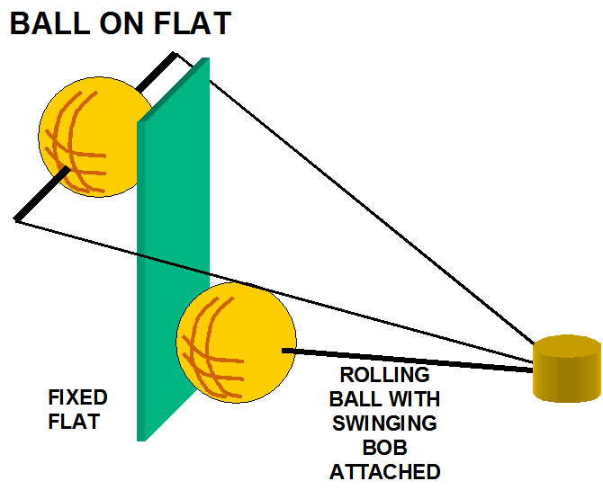
Ball
on Plate:

Most
constructions seem to end up with this class of pivots in a Lehman gate style
seismometer. Instructions may go
like, “Put a hardened piece of steel such as a razor blade or tool steel on
the upright, and a hard point such as a ball-point pen tip (with tungsten ball)
in the end of the beam” for a low friction point.
The biggest drawback to the ball on plate pivot is the terrible tendency
for the pivot to slide sideways on the plate due to the side force of the force
vectors when the beam swings out of perpendicularity with the plate with as
little as 4.5 degrees deflection. Tremors
certainly don’t cause swings of this magnitude, but many long period Lehman
have significant tilts due to temperature, base shift, etc. and can easily
exceed these values. In order to
control this, most instructions suggest that the plate be “dimpled” with a
punch or some such. But a dimple
defeats the concept of low friction as the geometry invites the possibility of
the ball having to “slip” in the dimple in order for the beam to swing.
This is probably one of the worst choices, yet is the one of the most
common type of pivots used. A variety of materials can be used. SS, tungsten carbide and sapphire spheres are available. The
cheapest material for a counterface is to use a SS scalpel blade. Triangular
tungsten carbide tips for lathe tools are available, but buy the un-coated sort.
Some other factors which may
also give problems in amateur seismometers:
1)
A failure to design the suspension in such a way
that there are no vertical forces/loads trying to move the ball away from it's
point of contact. Any vertical load is liable to cause position creep in
operation, if not a catastrophic failure when a severe quake is experienced.
2)
A failure to provide a sufficiently hard
counterface. High tensile bolts are not hard enough. The counterface needs to be
fully hardened martensitic SS, tungsten carbide, or sapphire.
3)
A critical factor is trying to use bearings of too
small a diameter. For axial loads of 1 to 4 pounds, the minimum diameter is
~1/4". 3/8" to 1/2"
OD bearings are preferred. Note that the axial load on the arm is likely to be
~double the mass weight.
4)
Due to the ball rolling sideways in normal
operation, the center of rotation is not quite constant with changes of
deflection, although the errors are not large enogh to be a practical problem.
The spreadsheet allows insight into this phenomenon.
See ball on plate study.xls or ball on plate study.pdf for calculations.
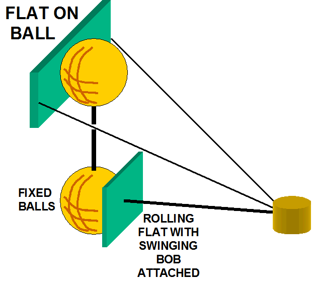
Plate
on Ball 
The simple reversal of position of the ball and plate has significant
positive effects. The locus trajectory error is more than 4 times better than
that of the ball on plate for comparable sizes.
The tendency to slip is almost entirely eliminated due to much better
geometric properties. In a
test, the arm was stable at angular deflections of 45 degrees.
For systems which use a plane
rolling on a ball, the angle of rolling contact that can lead to pivot point
skidding is reduced from the arm deflection angle by a factor of R / (R+L),
where R is the radius of the ball and L is the radius of gyration of the mass.
For a 3/8" ball and a 22" arm, this is this is 1/60.
See
plate on ball study.xls or plate
on ball study.pdf for calculations.
Crossed
Cylinder Suspension.
The geometry can be
viewed as a variation of the “plate on ball” if configured as described
here. These suspensions can provide
a greater load capacity than a sphere of a similar radius of curvature.
The rolling contact loss is lower than that of a sphere on a plane.
These can also make an excellent suspension for a long period Lehman. The
axis of rotation is well defined when the vertical rod is mounted on the support
column and the cross rod is mounted on the end of the arm.
Common materials are polished hardened martensitic SS and polished
tungsten carbide rods. It is
possible to buy surplus tungsten carbide drills for circuit boards and use their
shanks. Tungsten carbide center
drills and needle rollers are also available.
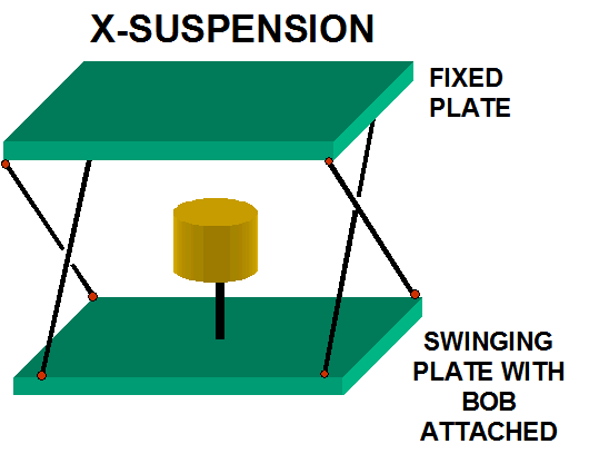
X-Suspension

During
the research for this note, the X-Suspension was found as a solution being used
in parts of the LIGO (Laser Interferometer Gravity-Wave Observatory) equipment
for vibration isolation of the detectors. So
this was added as a possible future avenue for a seismograph suspension.
Like the folded pendulum, a horizontal trajectory can be easily adjusted.
The downside is that due to the hanging nature of the suspension, it has
some sensitivity to the orthogonal axis. This
may be acceptable if one uses a sensing system that is insensitive to the
orthogonal movements such as Dr. Randall Peters' linear capacitance sensor.
Also it may be possible to implement it with an interesting
implementation of the X-roll pivots (see X-roll next).
Be aware that the equations solve for a flat trajectory of the center of
mass, but as that center of mass moves, there is a significant twist of the mass
during the swing.
See
Barton X-pendulum study.xls or Barton
X-pendulum study.pdf
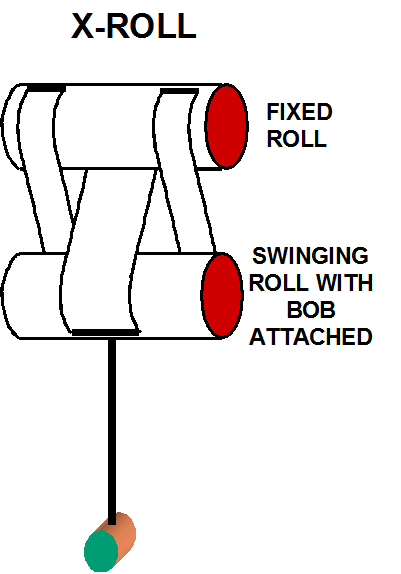
X-roll

During
a discussion on the PSN discussion list (webtronics.com ), a series of
experiments were executed to try to find low friction pivots.
These experiments included carbide rods rolling on other carbide rods
(crossed cylinder pivots) as discussed above.
But the pivot that came out the best in that series of experiments was
the X-roll. The study of its geometry also shows it to be one of the best
with low geometry error.
In
contemplating various seismometers using X-rolls as pivots it is likely that
that the X-suspension (see above) could be implemented as half X-roll pivots
with only 3 band/flexures total. A
folded pendulum using X-rolls would need 4 X-rolls with 12 bands total.
A normal Lehman could be implemented with two X-rolls and 6 bands.
I.e., generally the X-roll can be used to replace pivots and flexures in
other types of seismometers as long as the rolls can be kept in tension.
See
X-Roll study 2.xls
or X-Roll
study 2.pdf
Wire
flexures
Very
often wire flexures are used because of their simplicity, but there are some
major disadvantages:
1)
The end surface of the clamp plates need to be
machined and kept in alignment to a small fraction of the diameter of the wire
if lateral offsets/asymmetric bending effects are to be avoided. They need to be
made of material at least as hard as the wire. Collet mountings are preferred as
opposed to pairs of flat plates.
2)
Due to the high local stress and the short bending
radius, the frictional/anelastic losses are higher than in the bearings based on
rolling contacts.
3)
Due to the high
stress values wire fracture failures are to be expected. The wire is typically very highly stressed close to
the jaws of the clamp. It has to resist the clamp forces providing the axial
load as well as flexing. This can
lead to fatigue failures. If the length of a used suspension wire needs to be
adjusted, the whole wire should be replaced
4)
The high
stress of clamps can also cause bending and bending causes hysteresis.
5)
The geometry
of the trajectory is a complicated stress/strain relationship, often determined
by trial and error.
6)
The wire can
have severe secondary resonances and little resistance to orthogonal forces.
7)
Due to the requirement to minimize the wire
diameter, it may be relatively elastic to changes in axial loads, so the overall
length should be minimized. It can
also respond to resonance effects like the string of a musical instrument.
Note that D'Addario can
supply nickel plated 'piano' steel wire. This can be obtained from 0.008"
diameter upwards and it is resistant to corrosion.
Bendix
Pivots
Also
known as flexure pivots or cross-flexures are now available from http://www.c-flex.com/.
They are subject to significant, but well defined, center shift. See the
URL for C-Flex for more information. This
center shift can be mitigated by using very small gaps between the clamps such
as suggested by S-T Morrissey in his designs (see crossed foil later in this
paragraph), but this leads to higher stress/strain friction and possible
fractures. The positive quality of
these flexures is their good control and repeatability of position. They can be extremely stiff in the orthogonal axis.
Repeated flexing which only
slightly exceeds the elastic limit (as with crossed foils) will result in
hysteresis effects, possibly creating the results which Randall Peters is
investigating, and certainly adding a damping effect.
The commercial flexture pivot design specifies a significant hysteresis.
The variation of a crossed foil suspension is quite rigid when in
tension, but it cannot resist compression with thin foils. With wide foils, it
can have an appreciable resistance to axial loads.
However, the foils tend to bend sharply near the clamp edges. This causes
it to have some internal friction loss and it suffers from anelastic noise. The
centre of rotation is well defined but travels around a locus that is not the
cross-over point of the foils.
Rollamite
Bearings
Rollamite
Bearings are also a low loss special case of the X-roll bearings where the gap
is zero. Generally they’re used
in reverse where the lower roll supports the weight of upper roll and its
attached mass. There are variations
where the bands can be configured in tension to keep the rolls in contact while
hanging the load. They are
generally rigid in the orthogonal axis, but their biggest concern in seismology
use is that they might trap particles between the rolls leading to stiction/hysteresis
effects.
Some
Final Comments
Geometrically,
all pivots seem to have available a locus of sufficiently low theoretical error
in their normal implementation modes that this is unlikely to be the reason to
choose one over the other. But
there are other points that do make some choices much better.
In particular the stability and repeatability of the geometric pivot
point along with its rigidity in the orthogonal directions are important along
with low friction/stiction loss.
In the attached papers of some actual pivot tests, loss of crossed rods and loss of zero torque suspensions, Meredith Lamb found that rolling foil suspensions came out tops in the low loss tests followed by crossed wire/flexures that are ~ 2x better than balls on flats (or vice versa) that are ~ 2x better than crossed rods.
Other
experimenters have found rolling foils are
better than
rolling wires, which were better than crossed cylinders, which were better than
ball on a plane, which were better than ordinary crossed foils, which were
better than single foil Cardan suspensions.
Unsatisfactory
'suspensions'.
Do NOT use either a 'point in
a cup' or a genuine metal knife edge on a flat for a suspension system. Both
apply stresses over or near the maximum strength of the metal and even if they
work initially, they will not last long. If
the edges do not either roll over or shatter, they will dig into the counterface.
These systems are a common cause of poor performance in amateur
seismometers.
The 'knife edge' suspensions
used in chemical balances are 60 degree triangular agate rods, but the edges are
lapped to give the action of a very small cylinder rolling on a plane.
Notes
On Using The Spreadsheets
The
spreadsheets available here make possible the quantification of the locus errors
of many of the popular pivot systems. Note
that they require of bit of guess work. The equations figure the exact path of the bob and return a
comparison to the path generated by the locus point you enter.
You have to tweak(optimize) the locus point to minimize the error being
indicated. Once you’ve done a few
estimates, it should only takes a few minutes to home in to the needed locus
point. The spreadsheets
are not locked so you can experiment with them as you please.
Enjoy.
Experiment!
last edit 2008/10/15 ref corr X-roll docs